Intermediate System to Intermediate System (IS-IS)
Intermediate System-to-Intermediate System (IS-IS) Protocol is an intra-domain Open System Interconnection (OSI) dynamic routing protocol specified in International Organization for Standardization (ISO) 10589. The protocol is designed to operate in OSI Connectionless Network Service (CLNS).
Connectionless Network Service (CLNS)
OSI CLNS is a network layer service similar to bare IP service. A CLNS entity communicates over Connectionless Network Protocol (CLNP) with its peer CLNS entity.
Integrated IS-IS
IS-IS was originally designed for use as a dynamic routing protocol for ISO CLNP and later adapted to carry IP prefixes in addition to CLNP (known as Integrated or Dual IS-IS) as described in RFC 1195.
IS-IS Terminology
- CLNP – Connection-Less Network Protocol (ISO 8473, the OSI connectionless network layer protocol, very similar to IP)
- ES – End System (The OSI term for a host)
- ES-IS – End System to Intermediate System Routeing Exchange Protocol (ISO 9542 – OSI protocol between routers and end systems)
- IS – Intermediate System (The OSI term for a router)
- IS-IS – Intermediate System to Intermediate System Routeing Exchange Protocol (The ISO protocol for routing within a single routing domain)
- IP – Internetwork Protocol (an Internet Standard Network Layer Protocol)
- IS-IS Hello – An Hello packet defined by the IS-IS protocol (a type of packet used by the IS-IS protocol)
- ISH – An Hello packet defined by ISO 9542 (ES-IS protocol). Not the same as IS-IS Hello.
- LSP – Link State Packet (a type of packet used by the IS-IS protocol)
- NSAP – Network Service Access Point (a conceptual interface point at which the network service is made available)
- SEL – NSAP Selector (the last octet of NSAP addresses, also called NSEL)
IS-IS and OSPF
Both Link State Protocols use the Dijkstra SPF Algorithm to calculate loop-free routes. OSPF is used purely within the TCP/IP environment and used in both Enterprise and ISP environment. IS-IS is predominantly used in ISP environment.
- OSPF uses IP protocol 89 as transport.
- IS-IS is directly encapsulated in Layer 2.
IS-IS Network Types
Broadcast
- It is used on multi-access interfaces like Ethernet.
- Designated Intermediate System is elected (DIS) within a brodacast network, similar to OSPF DR but there is no backup DIS is elected in IS-IS.
- DIS is elected based on Highest priority and Highest SNPA (MAC) address.
- DIS election is preemptive.
- DIS performs flooding of LSA updates to a multicast address. That address is different depending on the Level:
- 01-80-C2-00-00-15 for Level 2 adjacencies
- 01-80-C2-00-00-14 for Level 1 adjacencies
- Flooded LSP are not ACK in a broadcast network. The DIS periodically sends out the CNSP (Complete) update. By default it’s 10 seconds and can be changed using the command isis csnp-interval.
Point-to-Point
- Used where two routers are connected in point-to-point fashion i.e Serial link. It can be used on an Ethernet link also when only two routers are connected.
- Cisco recommends using point to point type for better convergence.
- Each LSP has to be ACKed by PSNP. If one is not ACKed, the retransmit timer will trigger a retransmit.
- L1 and L2 LSPs are directly sent to the neighbor.
- No DIS election is done on point to point.
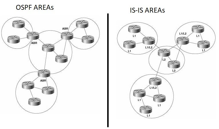
IS-IS Areas
Both IS-IS and OSPF use areas to create a hierarchical topology, but there is a fundamental difference exists in the way in which the two protocols define their areas. OSPF area borders are marked by routers where some interfaces of a router are in one area, and other interfaces are in another area. When an OSPF router has interfaces in more than one area, it is an Area Border Router (ABR).
With IS-IS, an individual router is in only one area, and the border between areas is on the link that connects two routers that are in different areas. This is in contrast to OSPF, in which the area borders are within the Area Border Routers (ABRs). The reason for this difference is that an IS-IS router generally has one network service access point (NSAP) address, and an IP router generally has multiple IP addresses.
An intermediate system can be a level 1 (L1) router, a level 2 (L2) router, or both (L1/L2). L1 routers are analogous to OSPF nonbackbone Internal Routers, L2 routers are analogous to OSPF backbone routers, and L1/L2 routers are analogous to OSPF ABRs.
With OSPF, inter-area traffic must traverse Backbone Area (Area 0) to prevent inter-area routing loops. All routers in the area maintain an identical link-state database for their own Area and Area Border Routers (ABRs) advertise LSA (Links State Advertisement) for destinations outside of its own area.
With ISIS, Every L1 router within an area (including the area’s L1/L2 routers) maintains an identical link-state database. Unlike OSPF ABRs, L1/L2 routers do not by default advertise L2 routes to L1 routers. Therefore, an L1 router has no knowledge of destinations outside of its own area. In this sense, an L1 area is similar to an OSPF totally stubby area. To route a packet to another area, an L1 router must forward the packet to an L1/L2 router. When an L1/L2 router sends its level 1 LSP into an area, it signals other L1 routers that it can reach another area by setting a bit known as the Attached (ATT) bit in the LSP.
Network Entity Title
IS-IS can be used to route TCP/IP, but IS-IS is still an ISO CLNP protocol. The packets by which IS-IS communicates with its peers are CLNS PDUs, which in turn means that even in an IP-only environment, an IS-IS router must have an ISO address. The ISO address is a network address, known as Network Entity Title (NET). While IP addresses are 32 bits long and are normally written in dotted quad notation (such as 192.168.1.1), NETs can be 8 to 20 bytes long, but are generally 10 bytes long and are written as shown in this example:
49.0001.1921.6800.1001.00
The NET address consists of three parts:
Area identifier: The first three bytes are the area ID. The first byte of this example — 49 is the address family identifier (AFI) of the authority, which is equivalent to the IP address space that is assigned to an autonomous system. The AFI value 49 is what IS-IS uses for private addressing, which is the equivalent of RFC 1918 address space for IP protocols.
The second two bytes of the area ID – 0001 represent the IS-IS area number. In this example, the area number is 1.
System identifier: The next six bytes identify the node (that is, the router) on the network. Although you can choose any value for the system identifier, a commonly used method is to use binary-coded decimal (BCD) which involves taking the router’s IP address (the address you assigned to the loopback interface), filling in all leading zeros, and then re-positioning the decimal points to form three two-byte numbers.
In this example, if you pad the IP address 192.168.1.1 with zeros, the result is 192.168.001.001. Rearranging the decimal points gives you 1921.6800.1001.
NET selector: The final two bytes are the NET selector (NSEL). For IS-IS, they must always be 00, to indicate “this system.”
Neighbors and Adjacencies
IS-IS routers discover neighbors and form adjacencies by exchanging IS-IS Hello PDUs. The type of router (L1-only, L2-only, or L1/L2) influences the type of adjacency that is formed, and the area IDs configured on the two neighbors in question.
The following rules apply:
- Two L1-only routers form an L1 adjacency only if their AIDs match.
- Two L2-only routers form an L2 adjacency, even if their AIDs are different.
- An L1-only router forms an L1 adjacency with an L1/L2 router only if their AIDs match.
- An L2-only router forms an L2 adjacency with an L1/L2 router even if their AIDs are different.
- Two L1/L2 routers form both L1 and L2 adjacencies if their AIDs match.
- Two L1/L2 routers form only an L2 adjacency if their AIDs do not match.
IS-IS Metric
IS-IS supports four different metric values – Default Metric, Delay, Expense, Error. Cisco IOS supports only default metric which has a default value of 10. The default metric is always set to 10 irrespective of the interface type (GigE or Serial etc.).
IS-IS Metric Styles
Narrow
- Default metric type.
- Metric default is 10 for each interface.
- Range for narrow metric range for an interface is 1 to 63 (6 bits).
- The maximum total value of all hops can be 1023 (10 bits)
Wide
- Wide metric type expands the metric to use 24 bits for TLV-22.
- The new metric style, link metrics can have a maximum value of 16,777,215 with a total path metric of 4,261,412,864.
- Cisco recommends running the wide metric style.
- If there is a mismatch between metric styles, the adjacency will be maintained, but routes will not be accepted with different metric style.
- Wide metric is required for MPLS TE and Multi topology configuration.
Transitional
- One way to transition to a different metric-style is by configuring all routers to metric-style transitional.
- Once all routers are sent you can change to either narrow or wide style.
- During the transitional phase, both types will be recognized.
IS-IS Topology Types
Single Topology – Single Topology IS-IS is used when multiple protocol stacks, such as IPv4 and IPv6, are configured in an identical 1:1 basis on all interfaces in the topology. It allows a single SPF calculation to apply to both protocol stacks at the same time, simplifying the database calculation and protocol overhead of IS-IS. By default, IS-IS instances runs in Single Topology mode with regular Cisco IOS, and Multi Topology mode with Cisco IOS XR. These modes are not compatible with each other and must be configured to match, or to run in transition mode.
Multi Topology – This method is used when transitioning to IPv6 or when different routing topologies are necessary for IPv4 and IPv6 address family. Each protocol stack maintain separate database structures and use separate SPF runs, which means that one topology is independent of another.
IS-IS Authentication
- Clear Text
- MD5